
Need Bollard Solutions?
Talk to our engineers about your security requirements.
Retractable Bollard Power Supply and Electrical Design: Cabling, Voltage Drop and Backup
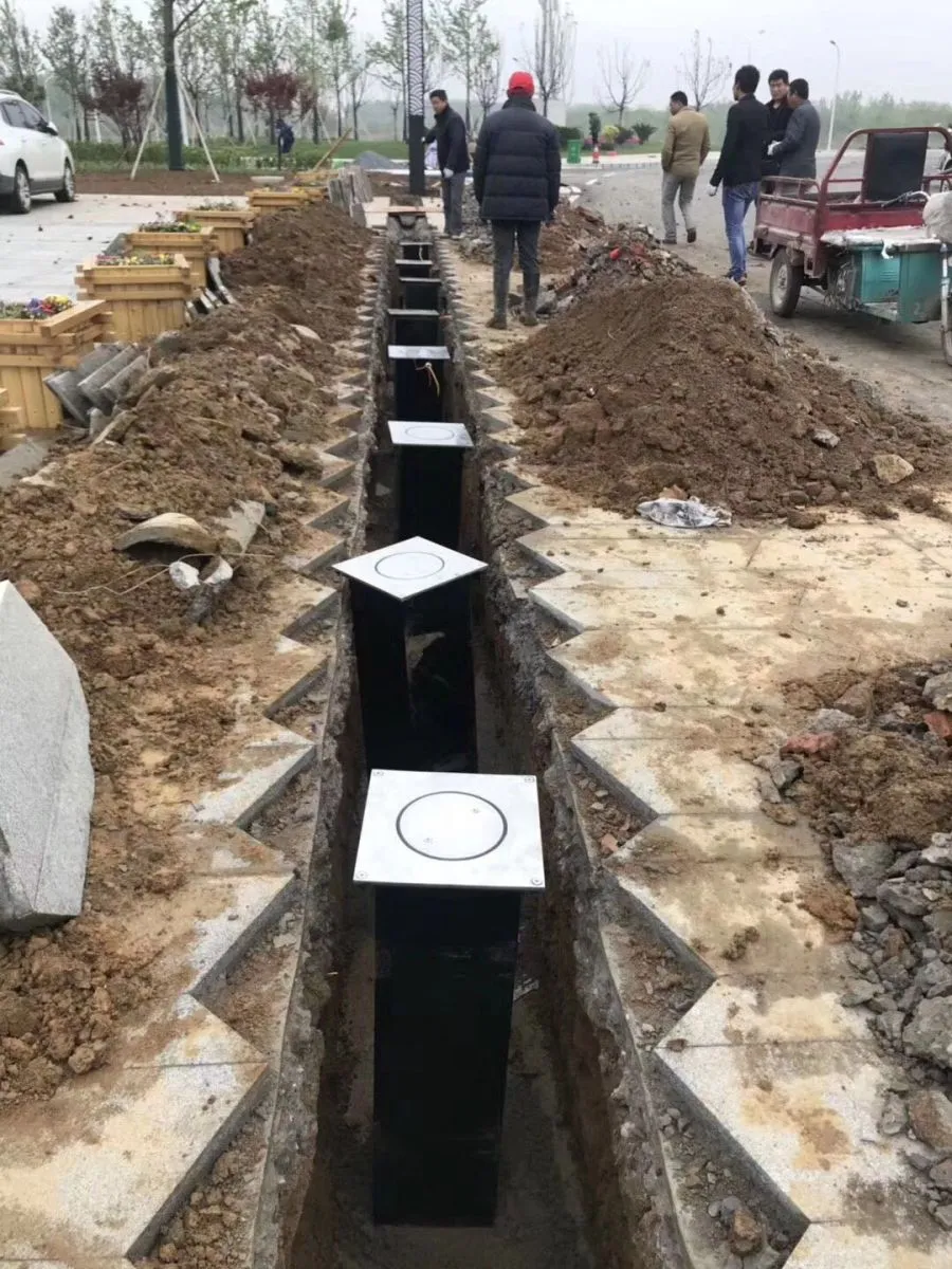
Why electrical design decides whether a bollard lane works
Most retractable bollard failures reported in the first year are not mechanical. They are electrical: a motor that stalls at start-up because the cable run was too long, a controller that reboots during a lightning storm, a pit connector that fills with water, or a backup battery that has never been asked to move the bollard until the day the power failed. Bollard heads are visible and specified carefully; the supply, cabling and protection behind them are often left to the last week of a project. This guide sets out the electrical decisions that belong at design stage, in the order in which they affect the finished lane.
Know the load before you size anything
Bollard actuators fall into three families, and each has a different electrical signature.
- Electromechanical units use a 24 V DC or single-phase motor with a screw, spindle or rack drive. Current draw is modest, but the inrush at start-up is several times the running current, and the peak occurs exactly when the bollard is lifting against its own weight plus any ice, grit or sand lodged in the seal.
- Hydraulic units use a central hydraulic power unit (HPU) that drives several bollards from one motor. The electrical load is concentrated in one place, which simplifies cabling and maintenance, but the HPU needs its own dedicated supply and ventilation, and it should not share a circuit with lifts, compressors or welding equipment.
- Pneumatic units need a compressor and an air receiver, so the electrical design is really a compressor design: duty cycle, air quality and receiver volume decide how often the motor starts, and how often it starts decides the life of the contactor.
Whatever the family, obtain the manufacturer's values for continuous current, peak or locked-rotor current, the number of full cycles the actuator is rated for per hour, and the permitted operating voltage window. Design the supply around the peak current and the worst-case ambient temperature, not the average — a lane that trips a breaker every winter morning is usually a lane specified from the running current alone, at summer temperature.
Supply arrangements
| Supply type | Typical rating | Design notes | Suited to |
|---|---|---|---|
| Single-phase AC | 220–240 V, 50/60 Hz | Simplest to arrange; give the lane a dedicated circuit with residual current protection and a motor-duty breaker curve | One to three bollards, retrofit lanes |
| Three-phase AC | 380–415 V, 50/60 Hz | Preferred for hydraulic power units and long lanes; keep the phases balanced across single-phase actuators | Four or more bollards, industrial gates |
| Low-voltage DC | 24 V DC, switch-mode or battery | Inherently safer to install and easy to back up; voltage drop becomes the limiting factor over distance | Compact electromechanical units, distributed lanes |
| Off-grid solar | PV array, battery bank, charge controller | Size on worst-case winter insolation and daily cycle count, never on the annual average | Remote lanes with no mains supply |
Conductor sizing and voltage drop
Voltage drop, not thermal current rating, is what actually limits cable length. A conductor that satisfies the thermal rating of the circuit can still starve the motor at the far end of a long run, and a 24 V DC system has very little margin to lose in the first place. Compute the drop from the peak current, the round-trip length, the conductor cross-section and the ambient derating factor, then keep the result inside the manufacturer's permitted band; a working target is to hold the drop under roughly five per cent of nominal for low-voltage DC drives and under about three per cent for single-phase AC feeds. In practice this means stepping a run up from 1.5 mm² to 2.5 mm² or 4 mm² as it passes about fifty metres, and landing each bollard on its own fused spur so that a single fault cannot disable a whole lane. Leave spare cores and a pull cord in every duct: the second and third cable pulled through the same trench causes far more disruption than the first.
Protection, earthing and isolation
- Give the bollard group a dedicated circuit rather than tapping a shared socket circuit, and select the overcurrent device by curve as well as rating so that motor inrush does not cause nuisance tripping.
- Fit residual current protection appropriate to the installation. A bollard pit is a damp location, and leakage currents appear there long before a fault becomes dangerous to a person.
- Bond every metal bollard body, the control cabinet and the pit frame to the same earth electrode, and measure earth continuity after installation. Stainless steel in wet, chloride-rich ground is particularly vulnerable to galvanic corrosion between two poorly bonded earth paths.
- Install a surge protective device on the mains side where the site has overhead lines, a long outdoor feed or a history of storm damage. Surge events rarely destroy a controller outright; they corrupt its memory and its firmware instead, and the fault appears weeks later.
- Provide a lockable isolator within sight of the equipment so a technician can work on a bollard without leaving neighbouring units energised.
- Label every cable at both ends and keep the as-built supply diagram inside the control cabinet door.
Backup power and fail-safe release
Backup is a design decision, not an accessory. Three levels are common. The first is a battery inside each bollard head that lowers the bollard on power loss: compact, self-contained, but limited to a small number of cycles. The second is an uninterruptible supply in the control cabinet, sized to keep the whole lane operational for a defined period and to hold the controller alive so that event logs and remote diagnostics survive the outage. The third is a purely mechanical release that stores no energy at all, such as a manual pump valve, a hand screw or a keyed clutch.
Whichever combination is chosen, size the battery by cycles rather than by time. A lane used twenty times a day needs enough stored energy to complete the expected number of movements with a safety margin, calculated at end-of-life capacity rather than new capacity, and at the lowest temperature the site experiences. Decide the failure posture explicitly: fail-open where people must be able to leave, fail-secure where the perimeter must stay closed. Then test the release at commissioning while the bollard is holding back a load, not in the workshop with nothing to hold.
Ingress protection and the pit environment
The pit is the harshest part of the installation: standing water, silt, de-icing salt and condensation. Specify bollard heads and connectors to an ingress protection level suited to permanent immersion where flooding is realistic, use gel-filled or resin-sealed joints, and gland every cable entry rather than relying on sealant. Provide drainage — a permeable base, a sump or a connection to the site drainage — and slope the pit floor so that water leaves by gravity. Where the water table is high, a small submersible pump with a float switch protects the electronics better than any coating. Leave a service loop of cable long enough to lift the bollard clear of the pit without disconnecting it, and seal the pit lid so that surface water cannot run in.
Keeping power and data apart
Motor cables radiate. Run them in separate ducts from signal and network cables, cross them at right angles where they must cross, and hold a separation of at least 300 mm on parallel runs between power containment and data containment. Use shielded twisted pair for serial links with the shield earthed at one end only, so that the shield never becomes an antenna or a circulating current path. Terminate network cabling to standard and certify it: an intermittent link generates phantom faults that get blamed on the controller for months.
Commissioning and maintenance checklist
- Confirm supply voltage, phase rotation and earth continuity before energising the controller.
- Measure the starting voltage at the bollard, not at the cabinet, during a full lift cycle.
- Record the current draw of every actuator and compare it with the data sheet; a slowly rising figure is the earliest warning of a failing seal or a dry mechanical drive.
- Test the residual current device and the surge protector, and log the results.
- Simulate a mains failure and confirm the intended fail-open or fail-secure behaviour, including the manual release.
- Flood the pit deliberately and confirm that it drains.
- Re-check gland and connector torque after the first month, then annually, and re-test the emergency release each season.
How Guardix supports electrical integration
Guardix supplies lane-level electrical and control guidance alongside the hardware: the YC-01 and YC-02 automatic rising bollard series with low-voltage DC and single-phase options, the PM-HLC-S804B heavy-duty hydraulic bollard with its own power unit, shallow-mount models for sites with limited pit depth, and the Guardix control system with multi-channel panels, battery-backed emergency release, surge protection provisions and remote diagnostics. Our engineers review supply capacity, cable sizing, drainage and failure posture as part of project design, and OEM configurations are available for sites with unusual supply or cabinet requirements.
"We ask for one number on every project: the voltage at the bollard during the lift, with the pit as wet as it will ever be. It tells us more about the health of the lane than any drawing."
— Guardix Engineering Team